|
World Leader in Pipeline Technology and Equipment |
| BKW Home | Pig Switches | Tadpole Pig | Pigging Equipment | Anchors | Slug Catcher |
| Engineering Support | Custom Services | Roof Raising | Research & Development |
| Gas Gathering System For Sale | Download Articles |
|
Contact Us |
|
|
|||
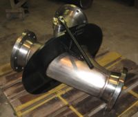
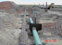
BKW has developed and patented pigging equipment
that advances pigging into the 21st Century.
 |
 |
|
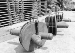
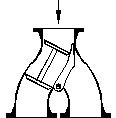
| Non-Sealing Switch One into two, manual or remote |
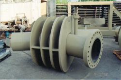
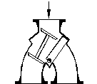
Sealing Switch
One into two, seals dead
side, manual or remote |
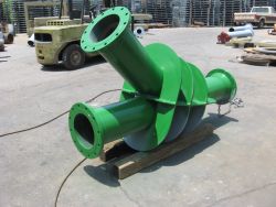
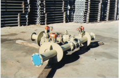
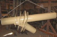
The Non-sealing Pig Switch will divert a pig into the pipeline requiring pigging without restricting the flow into the pipeline not requiring pigging. This process is used on multiple pipelines sharing one set of pig traps and on pipeline loops.
The Sealing Pig Switch is used when the flow is limited to the line being pigged. This requires the dead line to be sealed from the flow. This process is adaptable in tank farms where the lines are purged of product using air or nitrogen each time a tank is filled or emptied. Bi-directional pigs are required for this process.
Both types of switches will accommodate pigs that will travel through a long radius weld ell (3R). However, steel bodied pigs are not recommended because of possible damage as a result of run away pigs. The Sealing Switch will not switch from one side to the other without a zero pressure drop from the live line to the dead line.
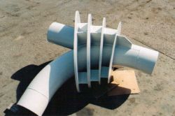
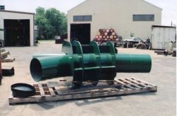
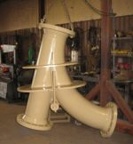
Both types of switches can be automated for remote operation and all switches are customized to the application. This includes in and out configurations such as forks, T's, Y's, and various combinations. In addition vents, drains and pig indicators can be installed on the switch.
Piggable Y and Pig Trap Comparison
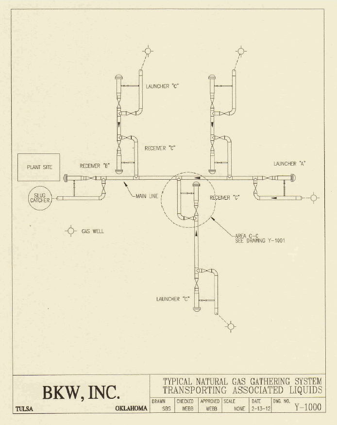
Drawing Y-l000 below shows a typical gas gathering system wiih pig traps for running pigs. Some gas gathering systems transport dry gas and are not equipped with pig traps since there is not an accumulation of liquids that need to be removed. However, in gas gathering systems that have associated liquids, pig traps are required because pigs are used for removing liquids accumulations, which in hilly country could cause gas lock.
A typical gas gathering system transporting associated liquids will have main trunk lines transporting gas from production to a plant to be processed into pipeline quality gas for sales. When large amounts of liquids are encountered, the plant will be equipped with a slug catcher that separates the liquids from the raw gas and stores the liquids for processing. The size of the slug catcher depends on the produced volume of liquids, the pigging frequency and the design of the gathering system.
The typical gas gathering system will have a flow line with a pig launcher "C" at each well and a pig receiver "C" at the main trunk line. A pig will be launched at the well and push the liquids into the main truck line. As each well flow line dumps liquid into the main trunk line, the volume of liquid accumulates to the capacity of the slug catcher. At this point, a pig is launched at "A" and received at "B" and removes all the liquid in the main trunk line.
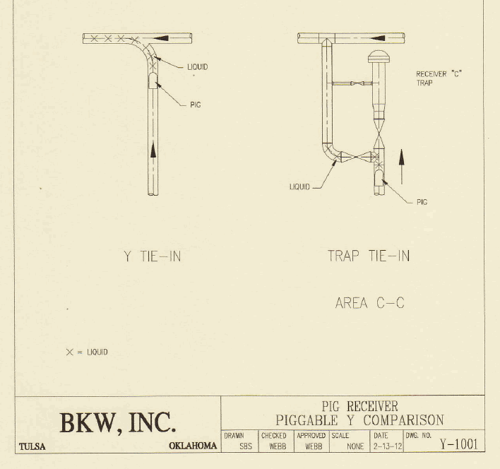
The slug catcher capacity and the pigging frequency can be reduced by installing piggable Y's in place of pig receivers "C" (see Drawing Y-1001). The piggable Y allows the pig from.launcher "C" to go into the main trunk line and push the liquids to receiver "B" at the plant site. This reduces the volume of the liquids received at the slug catcher, thus a smaller slug catcher. The pigs launched at each well site will push liquids to the plant site reducing the frequency of launching from launcher A on the main line.
The initial cost of the Y installed is approximately a fourth of the cost of a pig receiver. The Y can be buried, thus appurtenances are not visible aboveground. By eliminating a pig receiver, the pig retrieval expense is eliminated along with the aboveground appurtenances and the access road to the receiver trap. Also, by eliminating the pig trap, the maintenance of the trap and road is eliminated- ln addition, the Y radius is 3 diameter thus allowing for smart pig passage should this be required.
Pig / Y Compatibility
Please reference ASME paper titled "Art of Pigging" and Drawing No. 2010-100.
Bar tees and spheres, pigs and check valves and pigs and Y's all have to be compatible. The pigging article discusses the problems encountered when running spheres through a bar tee. This same problem exists when running pigs through check valves and Y's. When running a pig through a check valve, the pig and check valve are designed to be compatible. The distance between the entry and the exit of the check valve is called the bowl length. For check valves to pass pigs, this length has to be less than the length of the pig in order for the front cups on the pig to enter the exit before the back cups leave the entry. lf the pig was shorter than the bowl length, the weight of the clapper would hold the pig in the bowl and flow would bypass the pig.
Examine Drawing No 2010-100. Three-diameter radius bends are used in fabricating Y's to allow the passage of smart pigs. Three-diameter bends reduce the pressure drop required to move the pig through the bend; however, the longer the radius, the longer the bowl length and the more difficult to pass standard pigs because of low flow rates and excessive interference.
Two methods for correcting pig passage problems are the use of longer pigs and reducing the interference between the outside diameter of the pig and the pipe inside diameter. Lengthening the pig will prevent excessive blow by and thus maintain the required pressure drop across the pig to move it through the Y.
The interfererice should be reduced to red uce the pressure drop required to move the pig through the pipeline. For instance, in a'10-inch diameter pipeline, the flow area is around 79 sq. in. The force behind the pig at 10 psi pressure drop is 790 lbs. This is more than sufficient for good pipeline pigging. Should the pig hit a restriction, the pressure will increase until the pig overrides the restriction and the same applies when chasing liquids. Experienced pipeline operators know there are no two pipelines alike and there is not one operating procedure that is a "fits all". Start up operations requires experimenting with various pigs, launch frequencies, flow rates and pressure drops until the optimum operating procedure is achieved. ln gas gathering systems, flow conditions change, requiring pigging procedures to change, thus experimentation continues throughout the life of the system.

Click to view larger images.
|
|

|
| Typical Use of a Non-Sealing Switch | 10" ANSI 300 Sealing Switch under test | 10" ANSI 3 Way Sealing Switch with Air Operators |
|
|
 |
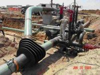 |
| 18" ANSI 600 Non-sealing Pig Switch |
(2) 28" ANSI 300 Non Sealing Pig Switch with Operators | 20" ANSI 600 'Y" |
|
BKW, Inc.
P.O. Box 581611 Tulsa, OK 74158
Phone: 918.836.6767 Fax: 918.836.0141
|
| BKW Home | Pig Switches | Tadpole Pig | Pigging Equipment | Anchors | Slug Catcher |
| Engineering Support | Custom Services | Roof Raising | Research & Development |
| Gas Gathering System For Sale | Download Articles |
|
Contact Us |
|
|
|||
| Website by PRO Designs | |||
